A smart project for smartphone user can be said about this DIY project. A specially designed android application is prerequisite for the efficient working of this project. As from the name it is understood that in this DIY project we are going to build a robot which can be controlled via Bluetooth communication. The purpose of the aforementioned app will be to give specific instructions to the robot. An Arduino board is used as the controller of the project which will be converting the communicated data to the robot.
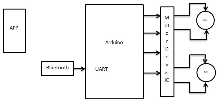
The block diagram will help you how to make the connections for this DIY project. The App block represents the smartphone with the specified application. The Bluetooth of the mobile phone should be enabled and paired with the Bluetooth module connected to the UART pin of the Arduino Uno board. The output of the Arduino will be given to a motor driver IC. The ‘M1’ and ‘M2’ DC motors are connected to the driver IC.
Android application- ArduinoRC
Working
The android app developed will send some code characters for the specific functions as required by the user to be performed by the robot. Since it is a basic one here the robot is asked to perform 4 functions namely: forward, backward, left and right movements. The user will send the directions using the app. For forward ‘F’, backward ‘B’, left ‘L’ and for right ‘R’ is sent through the app.
The data will be communicating with the robot through the Bluetooth device in both the systems. The smart phones have inbuilt Bluetooth module in them. Generally the range of Bluetooth is 10m. The device should be placed accordingly. If you want to increase the range go for higher end Bluetooth modules.
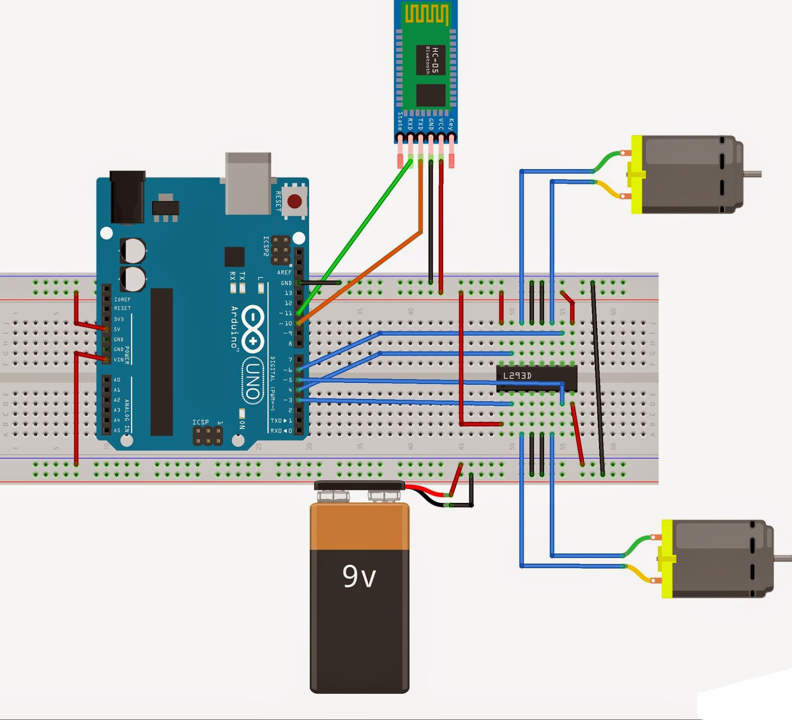
The receiver side Bluetooth module is connected to the UART (Universal Asynchronous Receiver Transmitter) pin of the Arduino board. The Arduino used here is Arduino Uno board an apt for the beginners. It is a robust one. The first timers will love this as you can easily play with the electronics and coding sections. It is based on ATmega328P.
The motor driver IC used here is L239D which can drive 2 motors simultaneously. The motor driver IC is required because the power generated from the Arduino board won’t be sufficient to drive a 12V DC motor. H-bridge is the concept behind the working of this IC.it has 2 H-bridges which are suitable for driving low current motors. M1 is for forward and backward movement and M2 for left and right side movement. The driver will provide corresponding digital inputs to the motor as specified by the user.
In short, when the user using the application type the specified character it gets communicated via Bluetooth to the Arduino board, the board will generate corresponding digital outputs. These outputs will be provided to the motor via the driver IC to move as per the desired direction.
A simple DIY project using the smart technologies which can be enhanced further can be a pivotal for the enthusiast to inspire more to learn.


Copyright © 2024 Mepits - Designed By Digiora


