Triac is a four layer three terminal power semiconductor device. Unlike the SCR, the Triac conducts in either direction when triggered. Bidirectional property of Triac is used in applications to regulate AC power. “Tri-ac” denotes three terminal AC switches.

Figure shows symbol and equivalent circuit of Triac. Equivalent circuit consists of two SCRs connected back to back in parallel form. It starts conducting when gate is triggered and continue till the current through the device is less than holding current. Triggering can be done by either a positive or negative voltage applied to its gate.
|
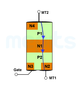
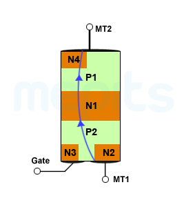
Triac ConstructionAs seen in the figure, Triac has six doped regions, which incorporate, two SCRs connected as inverse parallel in a single chip. As shown in the figure, the gate terminal makes direct ohmic contacts with both the N-type and P-type materials. Therefore, trigger pulse of either polarity can initiate conduction.
|
 |
Triac is a bidirectional device, the terminals are named as MT1 (Main Terminal 1) and MT2 instead of Cathode and Anode. Another difference from SCR is that, Triac can be triggered by both positive and negative current signals. A Triac can conduct in both directions and therefore, it has four modes of operations.
(i) MT2 and gate is positive with respect to MT1Current path is from MT2 to MT1 through P1, N1, P2, and N2. Now junctions P1-N1 and P2-N2 is forward biased and junction N1-P2 is reverse biased. Positive voltage at the gate (P2 region), forward biases P2-N1 junction and the depletion region is reduced, thus enabling the current conduction through the device.
(ii) MT2 is positive and Gate is negative with respect to MT1When negative voltage is applied at gate (now N3 region) junction P2-N3 is forward biased. More charge carriers are injected to P2, thus, decreasing the width of the depletion region. Current from MT2 to MT1, through the device, is now enabled. |
 |
(iii) Both MT2 and Gate is negative with respect to MT1Direction of current is changed when MT2 is negative with respect to MT1. From MT1 current flows through P2, N1, P1, N4 and reaches the other end MT2. Now junctions P2-N1 and P1-N4 is forward biased and junction N1-P1 is reverse biased. Negative voltage at Gate (N3 region) forward biases N3-P2 junction. This injects more charge carriers to P2 region, forward biases N1-P1 junction. Current conduction through the device is now enabled. (iv) MT2 is negative and Gate is positive with respect to MT1If gate is positive, the junction P2-N1 is forward biased, and more charge carriers are injected into it. Width of the depletion region is reduced, thus, enabling current conduction through the device. |
 |
V-I characteristics of Triac
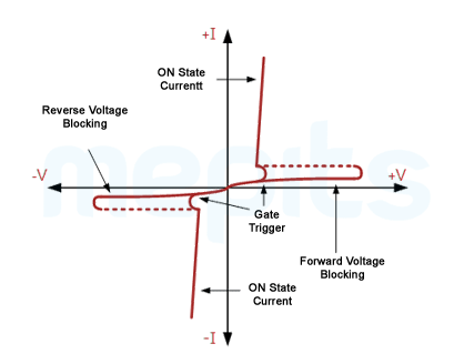
V-I characteristics of a Triac is similar to that of SCR. Since Triac can conduct current in both directions, a graph similar to the SCR forward characteristics is obtained in the first and third quadrant of Triac. Triac starts conducting when either positive or negative trigger is applied to the gate terminal.
|
 |
Sections