What is an RTOS?
Let’s imagine a person driving a car on a highway at a speed of 80 kmph. Unfortunately the car meets with an accident. The car was having air bag feature, so the airbag deployed at the appropriate time and saved the life of the driver. Thus the airbag is a very useful facility in a car which can assure safety of the driver. Now think the other way, the condition could have gone worse, if the airbag was a few seconds late to deploy. This shows that the airbag should be very accurate and its timing is a crucial factor. How the airbag stick to the timing constraint? Now let’s move to the world of RTOS.
RTOS is an operating system especially designed for real-time applications which allows the system to do multiple tasks at the same time. In RTOS, the performance of the system depends on the output and on the instant at which the output is obtained. Real time is the actual time during which an event or process occurs and the Operating system provides an interface between hardware and application programs. Real-time embedded systems operate in constrained environments where the main resources like memory of the system and processing power are limited. It should provide the services within extreme time limits to the users. For any RTOS there is a deadline to do the particular task or group of tasks. The system always maintains this deadline because missing a deadline can lead to drastic effects. So we can say that RTOS is an operating system that is specially designed to support real-time applications by providing accurate and reliable output within the time period.
An RTOS has to be designed in a way that it should possess a balance between its features and exactness of these features within the scheduled time limit and its dependability. For a best RTOS the context switching latency should be short. Now in the case of interrupts, the time duration between the executing the last instruction of the interrupt and executing first instruction of the interrupt handler should be minimal. This is called as interrupt latency. Moreover the time duration between execution of the last instruction of the interrupt handler and execution of the next task should also be minimal. This is called interrupt dispatch latency. Both the interrupt latency and interrupt dispatch latency should be predictable too. So in general the reliability of the mechanism within the specific time should be maximum. This enables processes to communicate with each other in a timely manner and provide the support for multitasking.
The most widely used RTOS include :
LynxOS
OSE
QNX
RTLinux
VxWorks
Windows CE
What is an Arduino?
The Arduino Uno is an open source microcontroller development board based on the ATmega328p. The Arduino Uno has
14 digital input/output pins
6 pins supporting PWM outputs
2 external interrupt pins
6 analog inputs
16 MHz crystal oscillator
USB connection
DC power jack
ICSP header
Reset button
Arduino contains everything for supporting the ATmega328 microcontroller. We can power the board connect it to a computer via USB cable or can directly use AC-to-DC adapter or DC battery.
The Arduino Uno is not using the FTDI USB-to-serial driver chip. The ATmega8U2 microcontroller chip is programmed as USB-to-serial converter and used in the Arduino uno. This makes it different from all preceding boards. The board is named "Uno" to indicate the release of Arduino 1.0. In Italian, the word “Uno” means one. The Arduino Uno version 1.0 is the reference version of the family and now the version 1.8.1 is available.
Background
Most of the operating systems allow multi-tasking. Multitasking is the process of executing multiple programs or threads at the same time. Practically, at any instant of time, each processor core can only be running a single program. Scheduler is the part of operating system which decides which program to run at what time. It allows the system to execute multiple tasks at the same time by continuously switching between each program. The scheduler is an important part in an RTOS since it is designed to provide a predictable and deterministic pattern of execution. This is very useful for any embedded system which has real time requirements.
In traditional real time schedulers, the key factor was assigning priority to the threads such that high priority tasks always precede over a low priority tasks. Hence the determination is achieved by allowing the user to accredit a priority to all threads in the execution. This allows the scheduler to run next thread based on priority. A Task is actually a thread of execution in FreeRTOS.
Getting Started
Make sure that any latest version of Arduino IDE is installed on the computer and the most recent FreeRTOS Library Release v9.0.0-1 is installed. If not download it from the following link and extract it to the libraries folder inside Arduino folder.
https://github.com/feilipu/Arduino_FreeRTOS_Library
Now open the Arduino IDE and go to library manager by following the steps:
Sketch → Include library → manage libraries
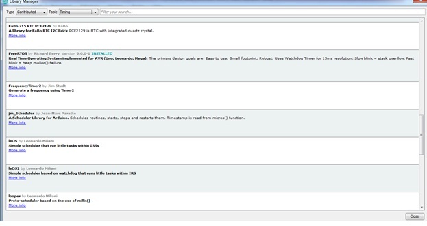
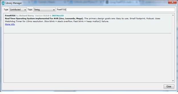
You can search the FreeRTOS Library from the Type: “Contributed” and the Topic: “Timing” in the library manager. You can see that latest version of freeRTOS installed as shown in the figure below.

Fig.1: Arduino library manager

Fig.2: RTOS version installed
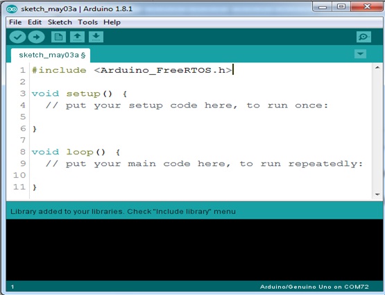
Now go to Sketch→Include Library in the Arduino menu, and make sure that the FreeRTOS library is incorporated in the program. A new empty program will look like the following.

Fig.3: New empty sketch with FreeRTOS included
Just Compile the program and upload it to the Arduino Uno and it can be seen how much of the flash memory is consumed by the FreeRTOS scheduler. It shown “Sketch uses 7228 bytes (22%) of program storage space” when compiled using Arduino v1.8.1 on Windows 7. At this time the FreeRTOS is running on the device.
Next Steps
Now simply by uploading one of the built in examples from Arduino, say the Blink sketch, with an elemental Real-Time Operating System simply by inserting the header for FreeRTOS as “#include <Arduino_FreeRTOS.h>” at the start of the program sketch. Now we will be having FreeRTOS running in the sketches.
To explore the features of multitasking let’s create a program combining two real time tasks within Arduino IDE. So we can combine any two basic programs, for example let’s choose one digital and analog examples. Let it be the program for led blinking and analog reading from one analog port. So we can combine led blinking program and analogRead program into one new program with two separate tasks in which both tasks execute their duties, handled by the FreeRTOS scheduler. This code can be found by following the steps File → Examples → FreeRTOS → Blink_AnalogRead or you can simply copy the following program and create a new sketch. Just upload it into Arduino and open the serial monitor. Now you can see that the controller is displaying the data fetched from its analog port and blinking the led simultaneously. This explains how effectively different tasks can be done together.
Program
#include <Arduino_FreeRTOS.h>

// define two tasks for Blink & AnalogRead

void TaskBlink( void *pvParameters );

void TaskAnalogRead( void *pvParameters );

// the setup function runs once when you press reset or power the board

void setup() {

  // initialize serial communication at 9600 bits per second:

  Serial.begin(9600);

  while (!Serial) {

    ; // wait for serial port to connect. Needed for native USB, on LEONARDO, MICRO, YUN, and other 32u4 based boards.

  }

  // Now set up two tasks to run independently.

  xTaskCreate(

    TaskBlink

    ,  (const portCHAR *)"Blink"   // A name just for humans

    ,  128  // This stack size can be checked & adjusted by reading the Stack Highwater

    ,  NULL

    ,  2  // Priority, with 3 (configMAX_PRIORITIES - 1) being the highest, and 0 being the lowest.

    ,  NULL );

  xTaskCreate(

    TaskAnalogRead

    ,  (const portCHAR *) "AnalogRead"

    ,  128  // Stack size

    ,  NULL

    ,  1  // Priority

    ,  NULL );

 // Now the task scheduler, which takes over control of scheduling individual tasks, is automatically started.

}

void loop()

{

  // Empty. Things are done in Tasks.

}

/*---------------------- Tasks ---------------------*/

void TaskBlink(void *pvParameters)  // This is a task.

{

  (void) pvParameters;

  // initialize digital LED_BUILTIN on pin 13 as an output.

  pinMode(LED_BUILTIN, OUTPUT);

  for (;;) // A Task shall never return or exit.

  {

    digitalWrite(LED_BUILTIN, HIGH);   // turn the LED on (HIGH is the voltage level)

    vTaskDelay( 1000 / portTICK_PERIOD_MS ); // wait for one second

   digitalWrite(LED_BUILTIN, LOW);    // turn the LED off by making the voltage LOW

    vTaskDelay( 1000 / portTICK_PERIOD_MS ); // wait for one second

  }

}

void TaskAnalogRead(void *pvParameters)  // This is a task.

{

  (void) pvParameters;

  for (;;)

  {

    // read the input on analog pin 0:

    int sensorValue = analogRead(A0);

    // print out the value you read:

    Serial.println(sensorValue);

    vTaskDelay(1);  // one tick delay (15ms) in between reads for stability

  }

}