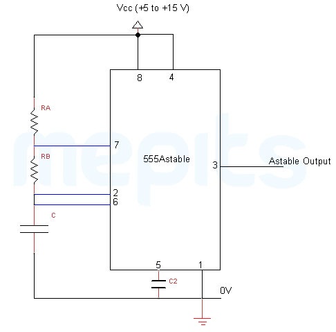
555 timer IC is one of the major component used for pulse generation and oscillator applications. The timer IC is generally an 8 pin IC were pin1 to pin8 is named as Ground, Trigger, Output, RESET, Control, Threshold, Discharge and Vcc. The IC has three operating modes: Astable, Monostable and Bistable.555 IC as an astable multivibrator is a continuous rectangular wave generating circuit. No input or external trigger is required to change the state of the output. Due to this reason, the astable multivibrator is called as a free running multivibrator. Based on its applications, it is also named as astable oscillator and square wave generator.
Note: Multivibrators more details....
Astable mode of the 555 IC is achieved by connecting the resistors R1, R2 and the capacitor C1 to the timer IC as shown in the figure. R1 is connected between pin4 and pin7.While R2 is connected between pin7 and pin6 with the pin2 as a common node. Connection of the capacitor C1 is between pin1 and pin6.The output produced by the astable circuit is not stable in both the HIGH and the LOW states and it continuously switches from one state to the other. The timing (time period) during which the output is either high or low is determined by R1, R2 and C1.

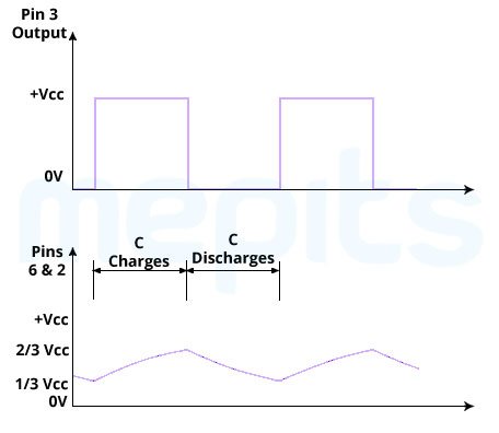
An astable 555 timer circuit usually contains an SR flip flop, two comparators, a NPN transistor and few discrete components like resistors and capacitors for its operation. Initially, when the power supply is switched ON, consider that the SR flip flop is cleared with Q=0. At this stage, the discharging transistor will remain OFF since Q (Q=0) is connected to the base of the transistor. The capacitor, C will now charge through RA and RB to Vcc. Hence we can say that, the time constant required for charging is equal to (RA + RB) C. As the threshold voltage (capacitor voltage) becomes greater than 2/3 Vcc, comparator 1 will be HIGH. The comparator output is HIGH because the voltage at the non-inverting terminal is greater than the inverting terminal. Now S=1, R=0, Q=1 and Vout=0 for the flip flop.
This change in Q will turn the discharging transistor to ON condition. Capacitor C will now turn over to the discharging mode. The discharging takes place through the resistor RB. Hence the discharge time constant will be RBC. When the capacitor voltage becomes lower than 1/3 Vcc, comparator 2 will be HIGH.As a result, S=0, R=1, Q=0 and Vout=1.Discharging transistor will now turn ON and the next cycle of operation will begin.


For the 555 IC to operate as an astable multivibrator it is necessary to continuously retrigger the 555 IC after each and every cycle. This retriggering is achieved by connecting the pin2 and the pin6 together. This astable wave oscillator is useful in generating signals for digital circuitry, lamp flashers, sound generators and various other applications.
Let t1 and t2 represent the charge and discharge times of the astable multivibrator respectively.

were RA and RB are in ohms and C is in Farad.
Let T be the cycle time of the astable multivibrator.

The duty cycle is defined as the ratio of charge time constant (t1) to the total cycle time (T) and for the astable oscillator it is found to be:

The simple operation and less number of external components make the astable multivibrator using 555 IC a popular one. The perfect square wave output from the circuit makes it good for many applications. Easy to design, low cost and no external triggering are the other advantages. The disadvantage is that we cannot achieve a duty cycle less than or equal to 50% using this circuit. This problem can be solved by inverting the output or by using a diode parallel to RB.

A negative pulse is given to the trigger input of the multivibrator. Comparator of the 555 timer detects the input and causes the flip-flop output to change from a low to high state. Due to the change in state of the flip-flop output, pin7 discharge transistor of 555 timer will move to OFF condition. Now the timing capacitor charges through resistor R1. This charging will take place until voltage at pin6 of 555 timer reaches 2/3 Vcc. When 2/3 Vcc is obtained at pin6, comparator output will move to high. This causes the flip-flop to have a Low output. Now the Monostable multivibrator is waiting for the other input trigger to repeat the entire process of operation.