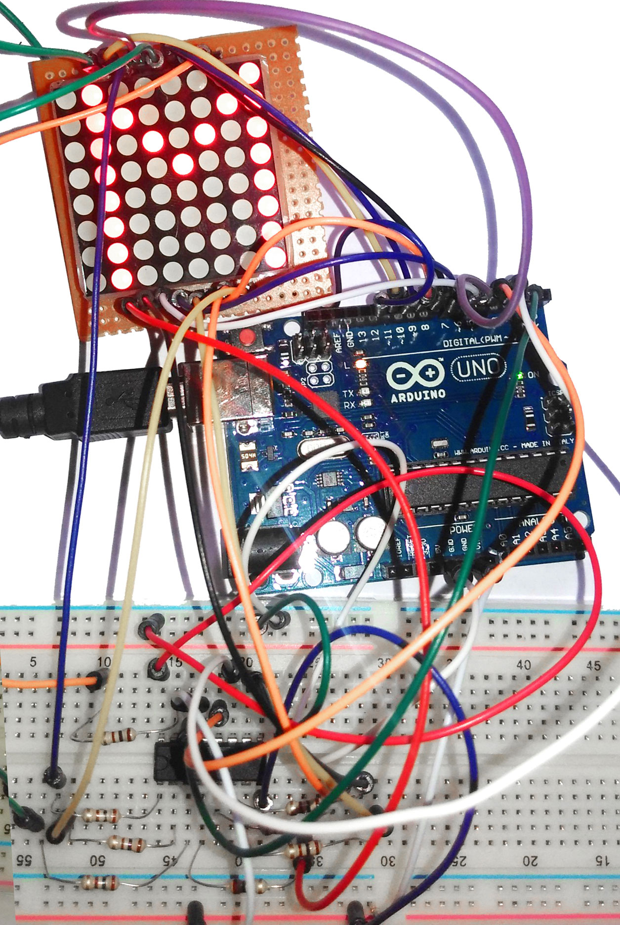
LED dot matrix boards are very popular means of displaying information in the form of static, animated images and text. Here let’s learn how to interface a dot matrix board with arduino UNO. The main aim is to display a character on the dot matrix board using the arduino and shift register IC.


Multiple LEDs are wired together in rows and columns. Here we are using an 8x8 dot matrix board. It will be having 8 rows and 8 columns. The rows are named as R1-R8. Columns are named as C1-C8. Here all the anodes are wired together in rows and all the cathodes in columns. Each LED in the matrix board is addressed by the row and column number.

Suppose we want to display the character A. So we have to select column C1 and deselect other columns. C1 is selected by making it to LOGIC 0 and C2-C8 is deselected by making it to LOGIC HIGH. Now C1 is active. The next step is to make the rows R2-R7 active. This is done by giving forward bias voltages to the rows. This process is repeated for rest of the columns and rows. By scanning the columns and making the LEDs ON; the image A will be displayed.
The table below shows how to select and deselect the rows and columns to display the character A.
|
ROW/COL |
C1 |
C2 |
C3 |
C4 |
C5 |
C6 |
C7 |
C8 |
|
R1 |
0 |
0 |
1 |
1 |
1 |
1 |
0 |
0 |
|
R2 |
0 |
1 |
0 |
0 |
0 |
0 |
1 |
0 |
|
R3 |
0 |
1 |
0 |
0 |
0 |
0 |
1 |
0 |
|
R4 |
0 |
1 |
0 |
0 |
0 |
0 |
1 |
0 |
|
R5 |
0 |
1 |
1 |
1 |
1 |
1 |
1 |
0 |
|
R6 |
0 |
1 |
0 |
0 |
0 |
0 |
1 |
0 |
|
R7 |
0 |
1 |
0 |
0 |
0 |
0 |
1 |
0 |
|
R8 |
0 |
1 |
0 |
0 |
0 |
0 |
1 |
0 |
HEX 0x00 0xFE 0x11 0x11 0x11 0x11 0xFE 0x00
Note: The hex values are written in the order as indicated by the arrow. These hex values are used in the program for displaying the character ‘A’.
Shift register IC, 74HC595N converts serial data to parallel data. The IC is used here to minimize the use of digital pins of arduino for controlling the display board.

In the program we will be displaying the characters. The program is attached as PDF below...