Tutorial by
Mepits

Interfacing On Atmel Microcontroller AT89S52 Development Board- 7 segment Display, LCD, Buzzer

Atmel AT89S51/52/53 – An Introduction

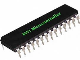
Atmel AT89S951/52/53 is basically designed to do all general purpose applications. This board contains hardware components, interfaces like LEDs, Buzzer, EEPROM, Keyboards, and LCDs etc. Also this board includes a COM port for serial communication using RS232.

Specifications of Atmel Microcontroller AT9S51/52/53 Development Board

  • Operating Voltage: 4.0 to 5.5 V.
  • 128x 8 bit Internal RAM
  • 4K bytes of  ISP Flash Memory
  • 2/3 16-bit Counters/Timers
  • Interrupt Source.
  • Operating Frequency: 0Hz to 33MHz.
  • UART
  • Watchdog timer
  • Program Memory Lock

Board Overview of Atmel AT89S51/52

Atmel Microcontroller  AT89S51/52/53 Development Board consists of

  • LCD display (2x16)
  • LED Interface
  • Buzzer Interface
  • 3x4 matrix keyboard with 12 keys
  • Adaptor, USB socket, DC power supply
  • 7 segment Display
  • I2C EEPROM, I2C RTC with (32.768 KHz) crystal oscillator and battery
  • Connector for PWM Output
  • RESET Button
  • Power LED Indicator
  • DB9 Connectors for UART
  • External Interrupts
  • IR Sensor and MAX232 are some other features included in the board

How to Interface a 7 segment Display with Atmel Microcontroller AT89S51/52/53 Development Board

Basically a 7 segment display in the board is a display consisting of illuminated segments to show the numerical symbols when it is powered ON. Each segment is connected to Port 2 of the AT89S51/52/53 microcontroller via a binary to decimal converter and current limiting resistor. As shown in Figure1 the board consists of 4 seven segments.

Program: Display 1,2,3,4 on the four 7 segment display respectively of Atmel Microcontroller AT89S51/52/53 Development Board

Program Code:

                Interfacing of Seven Segment with AT89S51/52/53

                                                                                      7 SEGMENT Display Program

Program Description:

  • Inorder to display the numbers 1,2,3,4 on the 7 segment display we have to use the Port 2 of the board.
  • To display 1 on the first 7 segment display, enter 0x71 to Port P2.
  • Similarly, to display 2 on the 7 segment display enter 0xB2, to display 3 enter 0XD3 and to display 4 enter 0XE4 .
  • To have a delay between the displays of numbers a delay function is called out.

Development of the Program in KEIL Microvision (µVision5) Software

  • Create Project.

Take “New µvision Project”. Create Project Name “ Sevensegment”.


  • Select the Microcontroller.

Since our microcontroller is Atmel ATS952/51/53 select it.


  • Create Source File.

Take “File” then New and enter the file name “ Sevensegment.c” and save.

  • Add files to project.

Now add the file “Sevensegment.c” to the project created.


  • Set Target.


  • Create HEX File


  • Build Project.

Compiling the program leads to the step of build project.

  • Simulate Program and download to the board.


How to Interface LCD with Atmel Microcontroller AT89S51/52/53 Development Board

Here we will be discussing how to interface a 16x2 LCD with Atmel ATS951/52/53 board. This will display 16 characters in one row. The pin configuration is given below.

Pin No:

Name

Function

Port P1.2

RS

Write data to be displayed LCD.

Port P1.1

R/W

Read or write data from or to LCD.

Port P1.0

E

Start the Module

Port 0 (P0.0-P0.7)

DBO-DB7

Give data to be displayed

Steps to display data on LCD

  • E=1; enable pin should be high
  • RS=1; Register select should be high
  • R/W=0; Read/Write pin should be low.

Send command to the LCD

  • E=1; enable pin should be high
  • RS=0; Register select should be low
  • R/W=1; Read/Write pin should be high.

Some useful commands for LCD Interfacing

  • 01 – Clear LCD screen
  • 06 -  Increment cursor
  • 80 -  Force cursor to beginning of 1st line
  • 38 - Use two lines of the display matrix.

Program Code

LCD Interfacing

                                                              LCD Program To display 'g'

How to Interface BUZZER with Atmel Microcontroller AT89S51/52/53 Development Board

Buzzer is just a piezoelectric material in the Atmel board. In this particular board, first set the port P1.4 to one. The sound from the buzzer is due to the piezoelectric diaphragm. The program is given below. Here a delay loop is created for the operation.

Program Code

        Interface with Buzzer

                                                                     Buzzer Interfacing Program

Conclusion

Atmel development board for the microcontroller interfacing is really good for different applications .Its capability to interface 7segment, LCD, LED and other interfaces is an advantage.

Note: Refer 8051 microcontroller to know more about  Embedded C tutorial using  Keil compilers …..

Note: Refer 8051 microcontroller to know more about How to interface computers Serial Port (RS232) with Atmel AT89S51/89S52 Microcontroller?

Related Items