Microcontroller is an entire computer manufactured on a single chip. They have all the features found in microprocessors. Built in ROM, RAM, input and output ports, serial ports, interrupts, timers and clock circuits are some of its basic features. 8051 microcontroller is the first basic microcontroller of the MCS-51 family and it was introduced by the Intel Corporation during the 1970s.
8051 microcontroller is an 8 bit microcontroller that can Read, Process and Write data of 8 bit. This type of microcontroller has many applications in the field of robotics, home appliances etc. The basic architecture of 8051 is shown below. It consists of:
On-chip RAM: Random access memory of 128 byte is used for data storage in 8051. RAM as a non-volatile memory consists of register banks, stacks for temporary data storage and some special function registers.
On-chip ROM: 8051 consists of 4KB ROM for program storage. ROM as a volatile memory helps in permanent data storage.
Timers and Counters: Timer helps in providing delay between the events. In 8051, there are two timer pins T0, T1. If these pins are used in the counter mode, we can count the external pulses. In T0, it is possible to store 16 bit data. This is done by storing the lower 8 bit in TL0 and the upper 8 bit in TH0. Similarly, we can store 16 bit data in T1 also. TMOD and TCON helps in the timer operation.
Serial Port: Inorder, to perform the serial communication, TXD and RXD pins are used. TXD pin is used for transmitting the serial data and the RXD pin is used for the transmission of the data. SCON register is used to control the operation of the serial communication.
Input and Output Ports: P0, P1. P2. P3 form the four ports of 8051 microcontroller. Each of the port is 8 bit wide. Port P0 is used as a Lower Order Address bus. Port P2 can be used as I/O port and higher order bus A8 to A15. Port P3 can be used as I/O pin and each pin of port 3 has special functions.
Oscillator – This is used to provide clock to the 8051 microcontroller. The crystal frequency can vary from 4MHz to 30MHz.
Interrupts - Interrupts are requests which are used to handle special events or routines known as Interrupt Service Routines. INT0 and INT1 are the basic interrupt pins used in 8051.
Arithmetic Logic Unit - This unit is used for arithmetic calculations.
Accumulator (A register) – This register is used for arithmetic operations.
B register – This is an 8bit register that is bit addressable and is used for two instructions only like MUL AB and DIV AB.
Program Counter – is a 16 bit register that helps to access address from 0000H to FFFFH. Program Counter is used to address the next instruction to be executed from the ROM.
Flag Bits and PSW register – The flag bits are used to indicate the arithmetic condition of the ACC. Program Status Word (PSW) is the flag resister in 8051. This register consists of four flags like Carry, Auxiliary Carry Flag, Register Select 1, Register Select 0, Parity Flag, Overflow flag.
Parity Flag (P) – If the accumulator registers consists of odd number of 1’s, then the parity flag will be set to 1. While, if the accumulator register consists of even number of 0’s, then the parity flag will be 0.
Carry Flag (CY) – This flag is set when there is a carry out from the D7 bit.
Auxiliary Carry (AC) – If there is a carry out after addition or subtraction operation from D4 bit, then the AC is set. Otherwise, AC is cleared.
Overflow Flag (OV) – This flag is set when the result of the signed operation is very big.
Register Select (RS1 and RS0) – They are used to change the bank registers.
Pin Diagram of 8051
Vcc – 5V supply
Vss – Ground
XTAL2/XTAL1 – Oscillator Input
Port0 (Pins 32-39) – AD0/AD7 and P0.0 to P0.7
Port1 (Pins 1 to 8) – P1.0 to P1.7
Port2 – (Pins 21 to 28) – P2.0 to P2.7 and A8 to A15
Port3 – (Pins 10 to 17) – P3.0 to P3.7
RST – Restart 8051
ALE – Address Latch Enable
PSEN – Program Store Enable
P3.0 – is used as RXD pin for serial communication.
P3.1 – TXD pin for Serial Transmit Data.
P3.2 – External Interrupt0 Pin, INT0
P3.3 – External Interrupt1 Pin, INT1
P3.4 – T0 – Clock Input for counter0.
P3.5 - T1 – Clock Input for counter1.
P3.6 – WR – Signal to write to the external memory.
P3.7 – RD – Signal to read from the external memory.
8051 Instructions
The 8051 instruction set is divided into 5 groups like:
Arithmetic Instructions
Branch Instructions
Data Transfer Instructions
Logic Instructions
Bit Oriented Instruction
1. Arithmetic Instructions
Subtraction, Addition, Multiplication and division operations are been performed by the arithmetic instructions of 8051 microcontroller. Some of the arithmetic instructions include:
2. Branch Instructions
3. Logic Instructions
4. Bit Oriented Instructions
Embedded C Programming Tutorial
Today, Embedded C language is used commonly to program microcontrollers. So it is important to know everything about Embedded C. Here we will be discussing the programming in Keil C compiler. Keil C51 compiler uses some keywords as given below for the ease of programming.
bdata: The variable chosen for the program will be stored in bit addressable memory of microcontroller.
unsigned char bdata v;
data / idata: The variable chosen for the program will be stored in the internal data memory of the microcontroller.
unsigned char data t;
code: Its used to store a constant variable like string or large integer numbers in code memory.
unsigned char code str=” compiler program";
xdata: The variable used in the program will be stored in the RAM memory of the controller.
unsigned char xdata k;
_at_: Helps to store a variable used in the program on a location in ram.
unsigned char data i _at_ 0x50;
pdata: This will store the variable in the program in the paged data memory.
unsigned char pdata l;
sbit: This keyword is used to define a special bit from SFR. It helps to set a particular variable to 1 in the program.
sbit Port1_1 = 0x90;
using: is used to define register bank for a function. sfr: It is used to define a 8-bit SFR (special function register).
sfr P1 = 0x40;
Memory Models 3 types of memory models are used in by the Keil C compiler for the programming.
Small
Compact
Large
Pointers in Keil C
Generic and Memory-specific pointers are commonly used as pointers in Keil C.
Generic Pointers
char *a;
Memory-Specific Pointers
The memory type and the pointer variable is indicated in the program statement.
What is PLC?
PLC also known as programmable logic controllers are basically digital computers designed especially for machine control, factory assembly lines and automation. The industrial automation techniques make use of PLC’s the most. The control of these devices vary from the general purpose computers, however, they were designed for
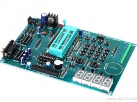
Atmel AT89S51/52/53 – An Introduction
Atmel AT89S951/52/53 is basically designed to do all general purpose applications. This board contains hardware components, interfaces like LEDs, Buzzer, EEPROM, Keyboards, and LCDs etc. Also this board includes a COM port for serial communication using RS232.
Specifications of Atmel Microcontroller
Atmel AT89S51/52 microcontroller has an integrated UART module for carrying serial communication. Serial communication makes use of asynchronous mode of operation. Serial port is defined as an interface between the PC and a device for transfer of data. AT89S51/52 with a serial port will allow reading and writing values to and from computer. Also no
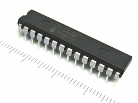
Peripheral Interface Controller(PIC) is a microcontroller from Microchip Technology. It is a Reduced Instruction Set Computer(RISC) that has been developed to achieve good performance from the use of a small optimized set of instructions. It comes in many different packagings that suit several simple and complex applications.
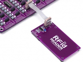
Radio Frequency Identification (RFID) is a system that uses radio waves to identify an object, person wirelessly. A typical RFID system consists of:
Antenna
Transceiver
Transponder
Basically, RFID operation is simple. Firstly, antenna of the RFID reader will be emitting radio signals which will activate the RFID tag or transponder. A