Do you ever wonder how to make a remote control car/toy or how to make a remote control robot? The objective of this project is to design a low cost remote control toy or robot. There are so many projects available to make RC toys. But here we are providing a simple circuit with low cost electronics components. DIY electronic projects like this will increase your passion to electronics.
The project “How to make a remote control car” is for students to make a low cost car by themselves. It is very useful to study the basics of wireless communication for electronics beginners. Mainly wireless car projects use two types of technologies Infra-Red (IR) and Radio Frequency (RF). IR remote control sends infrared rays to the car circuit. In case of IR remote control, line of sight with the receiving circuit is necessary and its range is only up to 10 meters. But in case of RF remote Radio Frequency waves plays the role, so signal can go through walls and are able to provide a range up to 35 meters.
In our project we are designing an RF remote control. For that we are using an ASK transmitter receiver module. Microcontroller is avoided in the circuit to make it cost effective. ASK module is used as the remote transmitter, two IC’s HT12E and HT12D is used for Encoding and Decoding. Circuit diagram and circuit explanation given below will make you confident enough to make a remote control car.
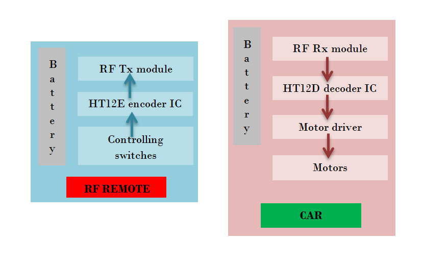
Controlling Switches: Four button switches are used in the remote control to move the car backward, forward, left and right.
HT12E Encoder IC: It is a 212 series encoder IC used for wireless communication applications. It is mainly used to convert 12 bit parallel data (8 address bits and 4 data bits) to serial out so that it can be transmitted using a transmitter Module.
RF Tx Module: 434 MHz ASK transmitter module for transmission. It is capable of providing a data rate of about 8kbps.
Battery: 3V button cell is used to power the remote.
RF Rx Module: A high sensitivity 434 MHz ASK Receiver module for receiving the data from remote control.
HT12D Decoder IC: It is a 1212 series decoder IC used for wireless communication applications. It converts the serial input to parallel out.
Motor Driver: L293D motor driver is used to drive two motors. L293D provides bidirectional drive current up to 600mA at voltages from 4.5V to 36V.
Motors: Here two BO motors are used which are driven by the motor driver L293D and both of them are connected to robotic wheels to move the car.
Battery: Receiver section need more power than the remote control circuit. So 9V/12V battery is required to power the circuit.
Only basic electronic components were used here for the project. All datasheets and link to buy the components online are provided below. Refer datasheets and get familiarize about the components used for the circuit before starting the DIY project.
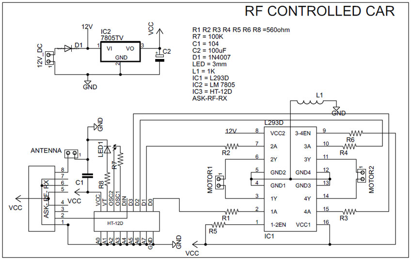

RC car circuit diagram with remote transmitter
Circuit design of this remote control car is simple and is of low cost as we are not using a microcontroller in it. So these type DIY electronic projects are very effective for hobbyists, students and for beginners in electronics field. Main components are two communication ICs (HT12D and HT12E) and an ASK RF transmitter receiver module. They are available in every local shop and online stores in a very low cost.
RC car circuit diagram with remote transmitter is designed in a compact way to make it as small as possible. Remote uses four button switches (S1, S2, S3, and S4) to control the toy. Digital data’s from the switches are encoded by the HT12E encoder IC and are transmitted to the receiver through ASK RF Module. When we press these switches, 4 data bits and 8 address bits are serially encoded and output through the pin “DOUT” is given to the 434 MHz Transmitter. Circuit is so simple due to the simple coupling of ASK module with HT12E and HT12D pair. Remote control is power by a 3V button cell.
Receiver section receives the signal with the help of 434 MHz ASK module and provides it to the decoder IC. “DIN” pin of HT12D gets the data from RF module and checks it three times before decoding. And if received address data matches with the encoder address data, then IC will decode the data bits and provides it directly to L293D motor driver. This driver is used to control the motors forward and backward according to the received signal. An LED is connected to the valid transmit pin of Decoder IC to indicate a valid transmission.
|
Left Motor Direction |
Right Motor Direction |
Direction of Car |
|
Forward |
Forward |
Forward |
|
Forward |
Backward |
Right |
|
Backward |
Forward |
Left |
|
Backward |
Backward |
Backward |
Highly optimized PCB design using Eagle Cad is provided below. Both the PCB design for remote control and car is designed as small as possible. Just print both these PCBs and solder it with the electronic components required. After soldering test all the components with a multimeter.

Remote PCB
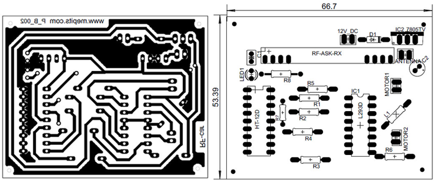
Remote Control Car PCB
This DIY project “how to make a RC car” uses only some basic electronics circuitry and mechanical design. So this project is very easy to make and very useful for students. Also this helps in learning about some basic electronics components and about Radio Frequency communication. As our circuit using low cost electronic components it is very helpful for students to learn electronics through practical knowledge.


Copyright © 2024 Mepits - Designed By Digiora


